- Processing Time
- Processes in 24 hours: Processing Time is guaranteed to be shorter.
- Typical Processing Time: 1-2 weeks
- Shipping Time
- FedEx Overnight: Within 1-4 business days
- DHL: Within 2-6 business days
- EMS: Within 4-15 business days
- UPS: Within 2-5 business days
- Hong Kong Post Airmail: Within 10-30 business days
- Payment Methods
-


The 10Gtek’s WDM series comprises a set of CWDM passive modules mechanically compatible with the 10Gtek’s CWDM chassis (part number CWDM-CHASSIS-2=) and a 1300/1550 nm splitter cable. Compared to the previous 1000BASE-CWDM series of passive filters, this new set of devices sports a greatly reduced insertion loss (up to 50 percent), "power-tap" ports to allow live monitoring and troubleshooting of the CWDM signals, as well as the mixing of 1300-nm CWDM signals on the same fiber infrastructures.
10Gtek’s CWDM solution applications:The 10Gtek’s CWDM solution based on CWDM gigabit interface converters (GBICs) and Small Form-Factor Pluggables (SFPs) and passive modules allows enterprise companies and service providers to provide scalable and easy-to-deploy Gigabit Ethernet and Fibre Channel services in their networks. The product set helps enable the flexible design of highly available and scalable multiservice networks.
The 10Gtek’s CWDM GBIC SFP solution is a convenient and cost-effective solution for the adoption of Gigabit Ethernet and Fibre Channel in campus, data-center, and metropolitan-area access networks.
Because of the flexibility of the passive devices, 10Gtek’s CWDM solution helps enable the deployment of a variety of topologies to multiplex up to eight different wavelengths on the same pair of fibers in protected or unprotected configurations. A connection between two endpoints is protected when it is associated with two channels (typically of the same wavelength) traveling on diverse fiber routes (for example, clockwise and counterclockwise in ring configurations or on separate fibers in point-to-point scenarios). Single-wavelength OADMs are equipped with two channels traveling different network paths (east and west) to offer redundancy or protection in rings. On the other hand, because CWDM-MUX8A= and CWDM-OADM4-x= have only a single network port (that is, one fiber path), two CWDM-MUX8A= or two CWDM-MUX4-x= are required to connect to redundant (protected) fiber routes.
Figures 1 through 10 illustrate the numerous protected and unprotected deployment scenarios of the Cisco CWDM solution with the Cisco WDM series of passive devices. The following conventions are adopted in the figures:
• N indicates the network port on the CWDM-MUX8A= and CWDM-OADM4-x=.
• P indicates the pass port on the part number CWDM-OADM4-x=.
• E and W indicate the network east and network west ports on the WDM-OADM1-xxxx=.
Figure 1. Point-to-Point Configurations with 4- Channel and 8-Channel Passive Devices

Figure 2. Point-to-Point Configuration with 4-Channel OADMs and Regeneration

Figure 3. Unprotected Bus Configurations with 4-Channel and 1-Channel OADMs With and Without Regeneration

Figure 4. Protected Hub-and-Spoke Configuration with 8-Channel Multiplexer/Demultiplexer and 4-Channel OADMs

Figure 5. Protected Hub-and-Spoke Configuration with 8-Channel Multiplexer/Demultiplexer and 4-Channel and 1-Channel OADMs

Figure 6. Protected Meshed-Ring Configuration with 4- Channel and 1-Channel OADMs

Figure 7. Protected Meshed-Ring Configuration with 8-Channel Multiplexer/Demultiplexer and 1-Channel OADMs

Figure 8. Mixing 1300-nm and CWDM in Point-to-Point Configuration with 1300-nm OADM Transparency

Figure 9. Mixing 1300-nm and CWDM in Point-to-Point Configuration with WDM Splitter Cable

Figure 10. Mixing 1300-nm and CWDM in Protected Rings with WDM Splitter Cable

Figure 11. WDM Splitter Cable for Non-CWDM Applications

Features and Benefits:The 10Gtek’s WDM series of CWDM devices offer numerous improvements over the previous generation of devices:
1. Lowest optical insertion loss (refer to Table 2 for details)-Compared to the previous generation of CWDM filters, the insertion loss is reduced up to 50 percent, depending on the model. This translates into much longer distances in both point-to-point and ring configurations.
2. Addition of "monitor" ports on every network port of multiplexers and OADMs as well as on the pass port on OADM4-x to simplify turn-up operations of CWDM networks-The monitor ports also can be used for in-service monitoring of the CWDM signals by means of an optical spectrum analyzer or a power meter.
3. Addition of two 4-channel OADM types for added flexibility: part number CWDM-OADM4-1 to cover the 1470, 1490, 1510, and 1530 channels and part number CWDM-OADM4-2 to cover the 1550, 1570, 1590, and 1610 channels.4. LC/UPC connectors
5. 1300-nm transparency-OADMs are now transparent to "traditional" 1300-nm channels. In other words, the 1300-nm signals can pass through the OADMs with a well-controlled loss. This feature helps enable configurations where CWDM can share the same fiber with traditional SONET/SDH services running on the 1300-nm wavelength.
6. Addition of a WDM splitter (or Y-cable) to multiplexer and demultiplexer channels in the 1300- and 1550-nm ranges-The WDM splitter cable can be used with CWDM optics or with standard 1550 optics. This Y-cable is another tool to integrate on the same fiber infrastructure CWDM with traditional SONET/SDH services running on the 1300-nm wavelength.
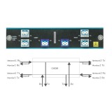
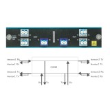
Figure 12 Front-Panel Port Configurations of the CWDM-MUX8A, CWDM-OADM4-x, and CWDM-OADM1-xxxx)

Figure 13. WDM Splitter Cable


Production Environment-
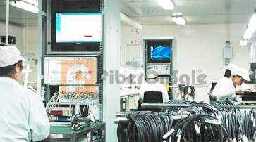
Production Environment -

Standardized Production Line -

Standardized Production Line -
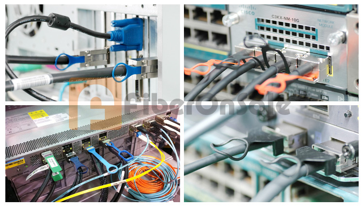
Compatible & Application Test -
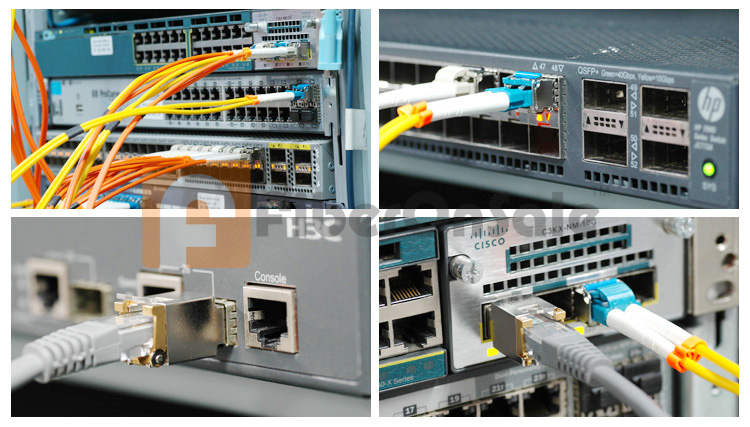
Compatible & Application Test -
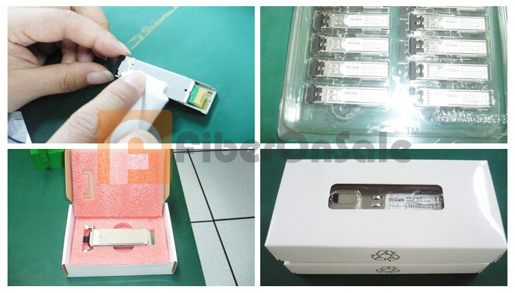
Packing -
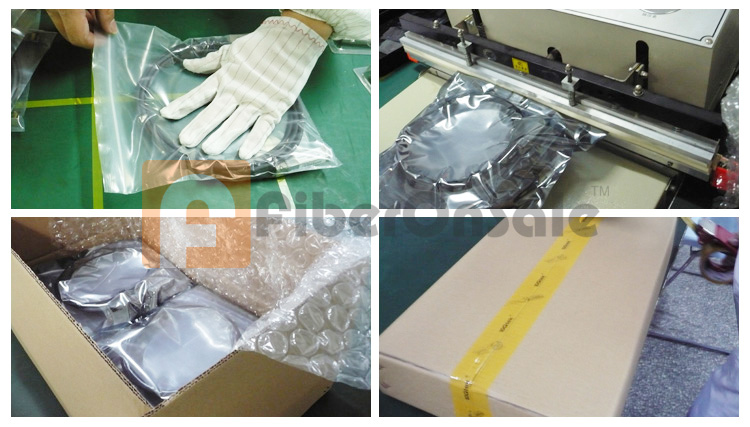
Packing -
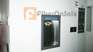
Environment Testing -
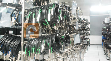
Warehouse -
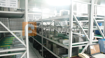
Warehouse -
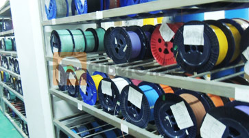
Warehouse


